
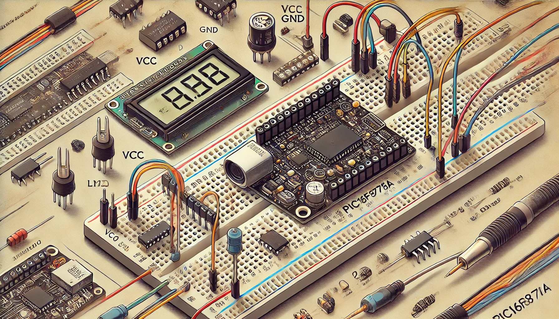

Temperature Monitoring System using PIC16F877A
Introduction
This project implements a temperature monitoring system using a PIC16F877A microcontroller and an LM35 temperature sensor. The system reads the temperature, displays it on a 16×2 LCD, and turns on an LED alert if the temperature exceeds a set threshold.
Real-World Applications
- Home automation (smart thermostats)
- Industrial temperature control
- Medical equipment monitoring
Learning Objectives
By completing this project, you will learn:
✅ How to interface an LM35 temperature sensor with a PIC16F877A
✅ How to read analog signals using the ADC (Analog-to-Digital Converter)
✅ How to display data on a 16×2 LCD in 4-bit mode
✅ How to implement an LED-based alert system
Required Components & Tools
Electronic Components
- PIC16F877A microcontroller
- LM35 temperature sensor
- 16×2 LCD display
- 10kΩ potentiometer (for LCD contrast adjustment)
- 220Ω resistor
- LED (Red) for temperature warning
- Breadboard & Jumper wires
- 5V DC power supply
Software & Programming Tools
- MPLAB X IDE
- XC8 Compiler
- PICkit 3/4 for programming
Background Concepts
LM35 Temperature Sensor
- Analog output proportional to temperature
- 10mV per °C (e.g., 25°C → 250mV)
- Requires ADC conversion to process data
ADC in PIC16F877A
- Converts analog signals to digital values (0-1023)
- 10-bit resolution
- Formula for temperature calculation: Temperature(°C)=(ADC Value1024)×500Temperature (°C) = \left( \frac{ADC\ Value}{1024} \right) \times 500Temperature(°C)=(1024ADC Value)×500
Interfacing a 16×2 LCD in 4-bit Mode
- Uses RS (Register Select), RW (Read/Write), and E (Enable) pins
- Displays real-time temperature readings
Circuit Wiring
Key Connections
LM35 to PIC16F877A:
- VCC → 5V
- GND → GND
- Vout → RA0 (AN0) (ADC input)
LCD to PIC16F877A (4-bit mode):
- RS → RD0
- E → RD1
- D4-D7 → RD2-RD5 (data pins)
- VEE (Contrast) → 10kΩ potentiometer
LED Alert:
- Anode → RC0 (Output pin)
- Cathode → GND (via 220Ω resistor)
Step-by-Step Implementation
1. Circuit Wiring
- Connect LM35 sensor to RA0 (AN0)
- Connect LCD in 4-bit mode
- Attach LED to RC0
2. Writing the Code (MPLAB XC8)
Here’s the fully commented C code:
#include <xc.h>
#include <stdio.h>

#define _XTAL_FREQ 20000000  // 20MHz Crystal

// Configuration bits
#pragma config FOSC = HS
#pragma config WDTE = OFF
#pragma config PWRTE = OFF
#pragma config BOREN = ON
#pragma config LVP = OFF

// LCD Pins
#define RS RD0
#define EN RD1
#define D4 RD2
#define D5 RD3
#define D6 RD4
#define D7 RD5

// Function Prototypes
void LCD_Command(char);
void LCD_Char(char);
void LCD_Init();
void LCD_String(const char*);
void ADC_Init();
int ADC_Read(int);
void Display_Temperature();

void main() {
    TRISA = 0xFF;  // Set Port A as input (LM35)
    TRISD = 0x00;  // Set Port D as output (LCD)
    TRISC0 = 0;    // RC0 as output (LED)

    LCD_Init();    // Initialize LCD
    ADC_Init();    // Initialize ADC

    while(1) {
        Display_Temperature();
        __delay_ms(500);  // Small delay for stability
    }
}

// Function to send command to LCD
void LCD_Command(char cmd) {
    RS = 0;        // Command mode
    D4 = (cmd >> 4) & 0x01;
    D5 = (cmd >> 3) & 0x01;
    D6 = (cmd >> 2) & 0x01;
    D7 = (cmd >> 1) & 0x01;
    EN = 1;
    __delay_ms(2);
    EN = 0;
}

// Function to send character to LCD
void LCD_Char(char data) {
    RS = 1;  // Data mode
    D4 = (data >> 4) & 0x01;
    D5 = (data >> 3) & 0x01;
    D6 = (data >> 2) & 0x01;
    D7 = (data >> 1) & 0x01;
    EN = 1;
    __delay_ms(2);
    EN = 0;
}

// Function to initialize LCD
void LCD_Init() {
    LCD_Command(0x02);  // 4-bit mode
    LCD_Command(0x28);  // 2 lines, 5x8 matrix
    LCD_Command(0x0C);  // Display on, cursor off
    LCD_Command(0x06);  // Shift cursor right
    LCD_Command(0x01);  // Clear display
}

// Function to display a string on LCD
void LCD_String(const char* str) {
    while(*str) {
        LCD_Char(*str++);
    }
}

// Function to initialize ADC
void ADC_Init() {
    ADCON1 = 0x80;  // Right justified, Vref = VDD
    ADCON2 = 0x89;  // Acquisition time, Fosc/8
    ADCON0 = 0x01;  // Enable ADC
}

// Function to read ADC value
int ADC_Read(int channel) {
    ADCON0 &= 0xC3;
    ADCON0 |= (channel << 3);
    __delay_ms(2);
    GO_nDONE = 1;
    while(GO_nDONE);
    return ((ADRESH << 8) + ADRESL);
}

// Function to display temperature
void Display_Temperature() {
    int adc_value = ADC_Read(0);  // Read from AN0
    float temperature = adc_value * 0.488;  // Convert ADC to Celsius

    char temp_str[16];
    sprintf(temp_str, "Temp: %.1f C", temperature);

    LCD_Command(0x80);  // Move to first row
    LCD_String(temp_str);

    if(temperature > 30.0) { // Temperature threshold
        RC0 = 1;  // Turn on LED
    } else {
        RC0 = 0;  // Turn off LED
    }
}
Troubleshooting & Debugging Tips
✅ LCD Not Displaying?
- Check contrast adjustment using the 10kΩ potentiometer
- Ensure correct pin connections (RS, RW, Enable, Data pins)
✅ Incorrect Temperature Readings?
- Verify LM35 sensor wiring (VCC, GND, Output to AN0)
- Use a stable 5V power source
✅ LED Not Turning On?
- Check RC0 is set as an output (
TRISC0 = 0;)
Extensions & Improvements
💡 Add a buzzer for a sound alert when temperature is high
💡 Send temperature data via Bluetooth/WiFi for IoT applications
💡 Log temperature values on an SD card for data analysis