

Smart Temperature and Humidity Monitor with LCD Display
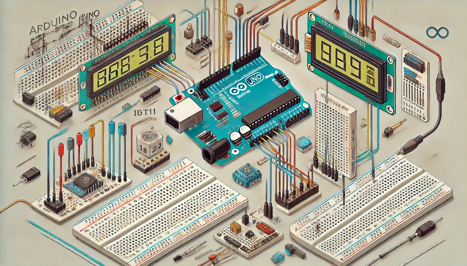
This project involves building a smart temperature and humidity monitor using an Arduino Uno, a DHT11 sensor, and an LCD display. The system reads temperature and humidity data from the DHT11 sensor and displays it in real time on the LCD. Such a device has real-world applications in home automation, greenhouses, server rooms, and weather monitoring systems.
Learning Objectives
By the end of this project, you will:
- Understand how to interface a DHT11 sensor and LCD with an Arduino.
- Learn how to use libraries to simplify data handling.
- Gain experience with data acquisition and real-time display techniques.
- Develop skills in wiring, debugging, and extending IoT systems.
Tools and Components
Tools
- Soldering iron and solder (optional for permanent connections)
- Breadboard and jumper wires
- USB cable for Arduino programming
- Computer with Arduino IDE installed
Components
- Arduino Uno (or any compatible Arduino board)
- DHT11 temperature and humidity sensor
- 16×2 LCD display (with I2C module for simplicity)
- 10kΩ potentiometer (if not using I2C module)
- Resistors (1kΩ and 220Ω for backlight control, if needed)
- Power supply (if not using USB power)
Background and Definitions
- Arduino Uno: A microcontroller board based on the ATmega328P chip. It has 14 digital pins and 6 analog pins for interfacing with sensors and actuators.
- DHT11 Sensor: Measures temperature and humidity. It uses a capacitive humidity sensor and a thermistor for accurate readings. Outputs data as digital signals.
- 16×2 LCD: A display module capable of showing 16 characters per line on 2 lines. It uses an HD44780 controller compatible with Arduino.
- I2C Communication: A two-wire protocol that simplifies LCD wiring by reducing it to four connections (VCC, GND, SDA, SCL).
- Libraries: Prewritten code that simplifies interfacing with sensors and devices. We’ll use the DHT and LiquidCrystal_I2C libraries.
Step-by-Step Guide
Step 1: Circuit Design
- Connections for DHT11 Sensor:
- Connect VCC to Arduino 5V.
- Connect GND to Arduino GND.
- Connect the DATA pin to Arduino Digital Pin 2.
- Connections for 16×2 LCD with I2C:
- Connect VCC to Arduino 5V.
- Connect GND to Arduino GND.
- Connect SDA to Arduino A4 (on Uno).
- Connect SCL to Arduino A5 (on Uno).
Note: If not using I2C, connect RS, E, D4-D7 pins to Arduino digital pins and use a potentiometer for contrast control.
Step 2: Install Libraries
- Open the Arduino IDE.
- Go to Sketch → Include Library → Manage Libraries.
- Search for DHT and install the DHT Sensor Library by Adafruit.
- Search for LiquidCrystal_I2C and install it.
Step 3: Write the Code
cppCopy code#include <Wire.h>
#include <LiquidCrystal_I2C.h>
#include "DHT.h"

// Define DHT sensor type and pin
#define DHTPIN 2     // Digital pin connected to the DHT sensor
#define DHTTYPE DHT11

// Initialize LCD and DHT
LiquidCrystal_I2C lcd(0x27, 16, 2); // LCD address 0x27, 16 chars, 2 lines
DHT dht(DHTPIN, DHTTYPE);

void setup() {
  lcd.begin();
  lcd.backlight(); // Turn on the backlight
  lcd.print("Initializing...");

  dht.begin();
  delay(2000); // Allow sensor to stabilize
  lcd.clear();
}

void loop() {
  // Read temperature and humidity
  float humidity = dht.readHumidity();
  float temperature = dht.readTemperature();

  // Check for valid readings
  if (isnan(humidity) || isnan(temperature)) {
    lcd.clear();
    lcd.print("Sensor Error");
    delay(2000);
    return;
  }

  // Display data on the LCD
  lcd.clear();
  lcd.setCursor(0, 0);
  lcd.print("Temp: ");
  lcd.print(temperature);
  lcd.print("C");
  lcd.setCursor(0, 1);
  lcd.print("Humidity: ");
  lcd.print(humidity);
  lcd.print("%");

  delay(2000); // Refresh every 2 seconds
}
Step 4: Upload and Test
- Connect the Arduino to your computer via USB.
- Select the correct COM Port and Board in the Arduino IDE.
- Upload the code.
- Observe temperature and humidity readings displayed on the LCD.
Testing and Debugging Tips
- LCD not displaying text:
- Check I2C connections and adjust the address (commonly
0x27or0x3F). - Ensure backlight and contrast settings are appropriate.
- Check I2C connections and adjust the address (commonly
- DHT11 not responding:
- Verify the wiring and sensor pin connections.
- Allow the sensor to stabilize (up to 2 seconds) before reading.
- Unrealistic readings:
- Ensure the sensor is placed in a stable environment without excessive heat or moisture.
Extensions
- Data Logging: Save the readings to an SD card for long-term analysis.
- Web Monitoring: Use a Wi-Fi module (like ESP8266) to send data to a server or mobile app.
- Alarm System: Add a buzzer to alert when temperature or humidity exceeds predefined thresholds.
- Graphical Display: Use an OLED or TFT screen for a more sophisticated display.
Summary
This project demonstrated how to use an Arduino to build a temperature and humidity monitor. By understanding the role of sensors, communication protocols like I2C, and real-time data handling, you are equipped to expand this project or apply the knowledge to other embedded systems applications.