
Welcome to the realm of Raspberry Pi GPIO control! In this guide, we delve into Python programming to command digital outputs, specifically LEDs. Illuminate your understanding as we navigate through the process of leveraging Python to exert control over Raspberry Pi digital outputs, bringing your projects to life with vibrant LED displays.
Embark on a journey into Raspberry Pi GPIO mastery! Uncover the art of configuring GPIOs as digital outputs through Python programming. Witness LED manipulation with gpiozero, unveiling the potential of controlling Raspberry Pi GPIOs for your projects.
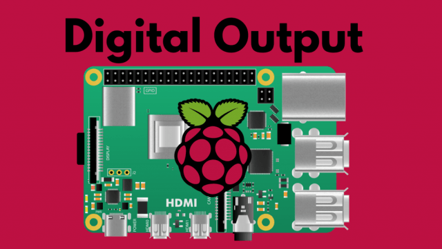
Prerequisites
Before delving into this guide, ensure you meet these prerequisites:
- Familiarize yourself with the Raspberry Pi board. If not, explore our Raspberry Pi Getting Started Guide [link].
- Proficiency in running and creating Python files on your Raspberry Pi. Check our detailed tutorial on Programming Raspberry Pi Remotely using VS Code (Remote-SSH) [link].
Unveiling the Raspberry Pi GPIOs
GPIO, short for General Purpose Input Output pins, facilitates the connection and control of electronic components such as LEDs, motors, and sensors with your Raspberry Pi. These pins enable the Pi to both receive and transmit information, enabling interactions with the external environment.
The majority of Raspberry Pi boards feature a dual row of 40 GPIO pins, and the pin layout is generally consistent across various models. This guide explores configuring Raspberry Pi GPIOs as outputs to command devices like LEDs, utilizing high (3V3) and low (0V) signals.
you might wanna check out this video in our Youtube Channel ( Light Sensor Triggers LED using Altium Designer )
Raspberry Pi GPIO Pin Configuration
GPIO Pin Identification Methods on Raspberry Pi
GPIO pins on the Raspberry Pi can be identified by their name, known as GPIO numbering or Broadcom numbering, and their corresponding pin physical number, reflecting the pin’s location on the header. For instance, GPIO 25 is associated with pin 22 (refer to the image below). Throughout this tutorial, we’ll use GPIO numbering (Broadcom numbering) for clarity.

Connecting the Circuit
Connect an LED to a Raspberry Pi GPIO. In this case, link the LED to GPIO 14 (pin 8). Choose alternative pins, excluding GPIO 0 and GPIO 1.
You will require the following components:
- Raspberry Pi Board (check Best Raspberry Pi Starter Kits)
- LED
- 220 Ohm resistor (or equivalent)
- Breadboard
Feel free to utilize the provided links for further information.

Managing Raspberry Pi Outputs with gpiozero
The gpiozero library offers various interfaces for common components such as LEDs, buttons, potentiometers, sensors, etc.
Rather than manually configuring GPIO properties for LED control, gpiozero provides a dedicated LED interface with practical methods. Alternatively, the DigitalOutputDevice interface supports general digital outputs, including LEDs. Let’s explore its functionality.
If you’re using Raspberry Pi OS, the gpiozero library is likely pre-installed; otherwise, execute the following command to install it:
python3 -m pip gpiozero
Generate a new Python file on your Raspberry Pi named “blinking_led.py” and paste the code provided below:
# Complete Project Details: https://RandomNerdTutorials.com/projects-raspberry-pi/

from gpiozero import LED
from time import sleep

led = LED(14)

# blinking an LED forever
while True:
  #set the led ON for one second
  led.on()
  sleep(1)
  #set the led ON for one second
  led.off()
  sleep(1)
How the Code Works
Keep reading to grasp the functionality of the code.
Importing Libraries
Initially, import the LED component from the gpiozero library for GPIO control. Additionally, import the sleep() function from the time module for code delays.
from gpiozero import LED
from time import sleep
You can opt for the DigitalOutputDevice component, which functions identically to the LED component.
from gpiozero import DigitalOutputDevice
Declaring the LED
Following that, instantiate an LED object named ‘led’ associated with GPIO 14, the pin to which the LED is connected. Modify the number if employing a different GPIO.
led = LED(14)Upon crafting and employing this LED object, your program recognizes GPIO 14 as an output switchable between HIGH and LOW. Post declaration, ‘led’ becomes the reference for GPIO 14, adaptable for managing components requiring HIGH (3.3V) and LOW (0V) signals, extending beyond LEDs.
Note: Opting for the DigitalOutputDevice component would involve the subsequent declaration:
led = DigitalOutputDevice(14)
While loop
Subsequently, for continuous LED blinking, establish a perpetual “while” loop with a constant True condition—ensuring indefinite runtime until manually halted. Post-loop declaration, indented lines signify Python’s recognition that this content executes as long as the while condition holds true.
# blinking an LED forever
while True:
  #set the led ON for one second
  led.on()
  sleep(1)
  #set the led ON for one second
  led.off()
  sleep(1)
Managing the Digital Output
The LED object provides two methods for toggling a GPIO—use on() to turn it on and off() to turn it off. This is demonstrated as follows:
led.on()
led.off()
The command led.on() activates GPIO 14, while led.off() deactivates it. The sleep() function introduces a one-second delay between each LED state, producing the blinking effect. The duration of the delay is specified in seconds as an argument to the sleep() function.
sleep(1)To summarize…
1) For managing a Raspberry Pi Digital Output, utilize the LED or the DigitalOutputDevice interface from the gpiozero library. Begin by importing it as shown:
from gpiozero import LED
or like this:
from gpiozero import DigitalOutputDevice
2) Specify the GPIO you intend to manage. If using the LED interface:
led = LED(GPIO_NUMBER_OF_YOUR_CHOICE)
Alternatively, if utilizing the DigitalOutputDevice interface:
led = DigitalOutputDevice(GPIO_NUMBER_OF_YOUR_CHOICE)
3) Utilize the on() and off() methods to activate and deactivate the GPIO, respectively.
led.on()

led.off()
Demonstration
Save your Python file, then execute it on your Raspberry Pi. Run the following command in the directory of your project file (replace with your file’s name)
python blinking_led.pyThe LED linked to GPIO 14 should exhibit a blinking pattern.

To halt the program’s execution, press CTRL+C.
Additional Handy Methods
Apart from on() and off(), the LED and DigitalOutputDevice interfaces offer more helpful methods.
toggle()
This method reverses the current GPIO state. Here’s an alternative script for LED blinking using the toggle() method.
# Complete Project Details: https://RandomNerdTutorials.com/projects-raspberry-pi/

from gpiozero import LED
from time import sleep

led = LED(14)

# blinking an LED forever
while True:
  led.toggle()
  sleep(1)
blink()
The blink() method cycles an LED on and off. You can specify on and off durations, as well as the number of blink cycles. Below is a script demonstrating LED blinking with the blink() method.
# Complete Project Details: https://RandomNerdTutorials.com/projects-raspberry-pi/

from gpiozero import LED
from signal import pause

led = LED(14)

# blinking an LED forever
led.blink()
pause()
“You can customize the blink() method using these parameters:
- on_time: duration in seconds the LED stays on (default is one second).
- off_time: duration in seconds the LED stays off (default is one second).
- n: number of blink cycles. Set to None for continuous blinking (default is None).
- background: if True (default), initiate background blinking and return immediately.”
Conclusion
In this guide, you acquired the skills to configure Raspberry Pi GPIOs as digital outputs, managing their states with the LED or DigitalOutputDevice interfaces in the gpiozero library. Additionally, you explored diverse methods to create blinking LED effects.