

🛠️ PLC Programming Exercise: Basic Conveyor Belt Control System
1. Introduction
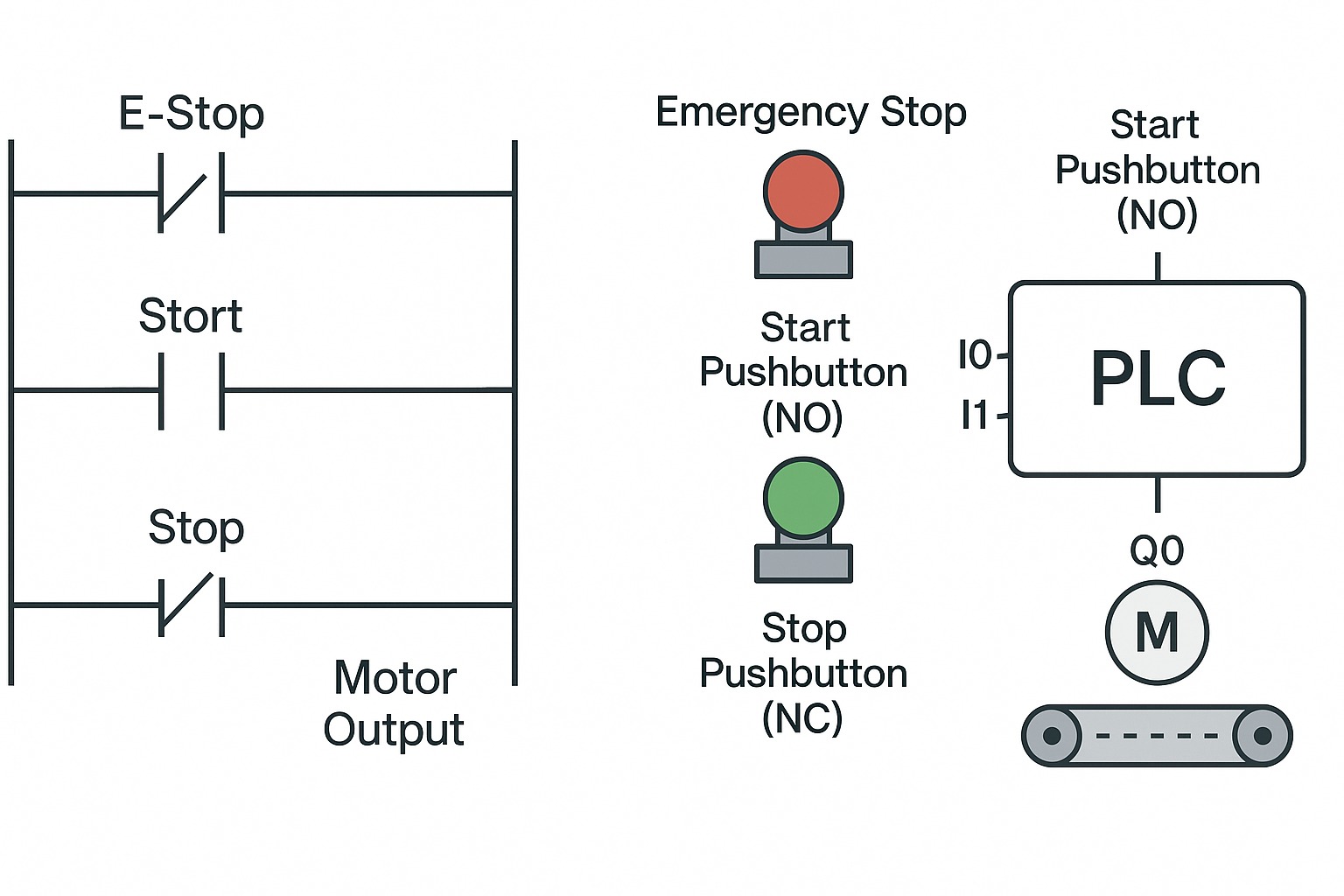
In this exercise, you’ll program a PLC to control a simple conveyor belt system. The system will use a Start button, a Stop button, and an Emergency Stop for safety.
This type of control is commonly used in factories, warehouses, and packaging systems to automate material movement while ensuring safety protocols are met.
2. Learning Objectives
By completing this exercise, you will:
- Understand and implement a latching circuit in PLC programming.
- Develop basic start/stop motor control logic.
- Implement a safety interlock using an emergency stop.
- Build confidence with PLC input/output programming concepts.
3. Tools and Components
You will need:
- A PLC device or simulator (examples: Allen-Bradley MicroLogix, Siemens S7-1200, or a simulator like LogixPro or TIA Portal).
- Start Pushbutton (Normally Open, NO).
- Stop Pushbutton (Normally Closed, NC).
- Emergency Stop Pushbutton (Normally Closed, NC).
- Motor or motor indicator (a simple lamp or relay output if simulating).
- PLC programming software (RSLogix 500, TIA Portal, or equivalent).
Input/Output Assignments:
- I0: Start Pushbutton (Normally Open)
- I1: Stop Pushbutton (Normally Closed)
- I2: Emergency Stop (Normally Closed)
- Q0: Motor Output
4. Background and Definitions
Before you begin, make sure you understand these concepts:
- Latching Circuit: A setup where an output remains ON even after the start input is released. It keeps itself active until a separate stop command is given.
- Normally Open (NO) Contact: A switch that allows current to flow only when it is pressed or activated.
- Normally Closed (NC) Contact: A switch that allows current to flow until it is pressed, which then interrupts the current.
- Emergency Stop (E-Stop): A safety device that immediately stops a machine when pressed, cutting off control power.
5. Step-by-Step Guide
Step 1: Setup I/O Tags
Assign your PLC inputs and outputs according to the following:
- Start Pushbutton (I0)
- Stop Pushbutton (I1)
- Emergency Stop (I2)
- Motor Output (Q0)
Step 2: Build the Ladder Logic Concept
The ladder logic should follow this basic rule:
- If the E-Stop is OK (input active),
- And if either the Start button is pressed OR the Motor is already running,
- And if the Stop button is NOT pressed,
- Then turn the Motor ON.
When the Stop button is pressed or E-Stop is triggered, the motor should immediately stop.
Step 3: Draw and Build the Ladder Logic
Textual Ladder Logic Description:
- Use a Normally Closed (NC) contact for E-Stop.
- Use a Normally Open (NO) contact for Start button.
- Use a Normally Closed (NC) contact for Stop button.
- Add a latching branch with the Motor output to keep it running after Start is pressed.
Pseudocode Version:
If (Emergency Stop OK) AND (Start Button Pressed OR Motor Already Running) AND (Stop Button NOT Pressed)
Then (Motor ON)
Step 4: Write the Ladder Logic (Explanation)
- Use an NC contact for the Emergency Stop (I2).
- Connect it to a branch:
- One side has an NO contact from Start (I0).
- The other side has an NO contact from Motor Output (Q0) (for latching).
- Both branches should join before an NC contact for the Stop Button (I1).
- If everything is satisfied, energize Motor Output (Q0).
6. Testing and Debugging Tips
When you test your project, follow these steps:
- Press the E-Stop. The motor should not start if E-Stop is open.
- Press the Start button. The motor should turn ON.
- Press the Stop button. The motor should turn OFF.
- Open (activate) the Emergency Stop while running. The motor should immediately turn OFF.
Common Problems to Watch For:
- If the motor doesn’t start: Check E-Stop and Start button wiring or programming.
- If the motor won’t stop: Verify the Stop button wiring is correct and the Stop contact is properly set as NC in the ladder logic.
7. Extensions: Challenge Yourself!
To further develop your skills, try adding:
- A timer that delays motor stop by 3 seconds after pressing Stop.
- An indicator light that shows when the motor is active.
- A motor reversing feature by controlling a second output.
- Speed control by integrating a VFD (Variable Frequency Drive) with analog inputs.
- Networking two PLCs to control multiple conveyors cooperatively.
🏆 Congratulations!
You’ve now built a professional, industry-standard PLC program that controls a conveyor belt with proper safety and operational logic. This skill is foundational for automation engineers, robotics specialists, and industrial electricians.