
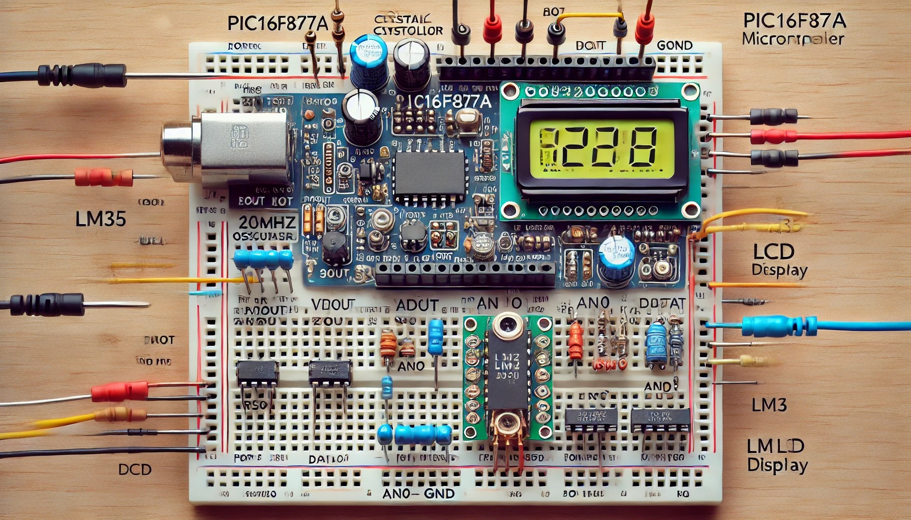

Temperature Monitoring System using PIC16F877A and LM35
1. Introduction
This project uses a PIC16F877A microcontroller and an LM35 temperature sensor to measure ambient temperature and display it on a 16×2 LCD. It can be used in home automation, weather stations, or industrial monitoring.
2. Learning Objectives
- Learn ADC (Analog-to-Digital Conversion) in PIC microcontrollers.
- Interface LM35 temperature sensor with a PIC MCU.
- Display sensor values on a 16×2 LCD using 4-bit mode.
- Understand troubleshooting techniques for embedded systems.
3. Tools and Components Required
Hardware:
- PIC16F877A microcontroller
- LM35 temperature sensor
- 16×2 LCD display
- Crystal oscillator (20MHz)
- Capacitors (22pF x 2)
- Resistors (1kΩ, 10kΩ for pull-up and contrast adjustment)
- Potentiometer (10kΩ) – For LCD contrast
- Power supply (5V DC)
- Breadboard & jumper wires
Software:
- MPLAB X IDE
- XC8 Compiler
- Proteus (optional for simulation)
4. Background & Key Concepts
LM35 Temperature Sensor
- The LM35 is a precision temperature sensor with an output proportional to temperature (°C).
- Output formula: Vout=10mV/°C×TemperatureV_{out} = 10mV/°C \times TemperatureVout=10mV/°C×Temperature
- Example: If Vout = 250mV, the temperature = 25°C.
Analog-to-Digital Conversion (ADC) in PIC16F877A
- PIC16F877A has a 10-bit ADC, meaning the digital output range is 0-1023.
- Conversion formula: Temperature=(ADC_value1023)×500Temperature = \left( \frac{ADC\_value}{1023} \right) \times 500Temperature=(1023ADC_value)×500
5. Circuit Diagram Explanation
- LM35 (Temperature Sensor) Connections:
- VCC → 5V
- GND → Ground
- Vout → AN0 (RA0) of PIC (Analog Input)
- 16×2 LCD Connections (4-bit mode):
- RS → RD0, E → RD1, D4-D7 → RD2 to RD5
- VSS → GND, VDD → 5V, RW → GND
- Contrast (V0) → 10kΩ Potentiometer (middle pin)
- Oscillator (20MHz) with Capacitors (22pF each) connected to OSC1 & OSC2 pins
6. Source Code (MPLAB X, XC8)
cCopyEdit#include <xc.h>
#define _XTAL_FREQ 20000000  // 20MHz Crystal Frequency

// LCD Pins
#define RS RD0
#define EN RD1
#define D4 RD2
#define D5 RD3
#define D6 RD4
#define D7 RD5

// Configuration Bits
#pragma config FOSC = HS    // High-speed Oscillator
#pragma config WDTE = OFF   // Watchdog Timer Off
#pragma config PWRTE = OFF  // Power-up Timer Off
#pragma config BOREN = ON   // Brown-out Reset On
#pragma config LVP = OFF    // Low Voltage Programming Off

// Function Prototypes
void LCD_Command(char);
void LCD_Char(char);
void LCD_Init();
void LCD_String(const char*);
void ADC_Init();
unsigned int ADC_Read(unsigned char);
void Display_Temperature();

void main() {
    TRISA = 0xFF;   // Set PORTA as input (for ADC)
    TRISD = 0x00;   // Set PORTD as output (for LCD)
    ADC_Init();     // Initialize ADC
    LCD_Init();     // Initialize LCD

    while (1) {
        Display_Temperature();
        __delay_ms(1000);  // Update every second
    }
}

// LCD Initialization
void LCD_Init() {
    LCD_Command(0x02); // 4-bit mode
    LCD_Command(0x28); // 2-line, 5x8 font
    LCD_Command(0x0C); // Display ON, Cursor OFF
    LCD_Command(0x06); // Auto Increment cursor
    LCD_Command(0x01); // Clear Display
    __delay_ms(2);
}

// Send Command to LCD
void LCD_Command(char cmd) {
    RS = 0;
    D4 = (cmd >> 4) & 1;
    D5 = (cmd >> 3) & 1;
    D6 = (cmd >> 2) & 1;
    D7 = (cmd >> 1) & 1;
    EN = 1; __delay_ms(1); EN = 0;

    D4 = cmd & 1;
    D5 = (cmd >> 1) & 1;
    D6 = (cmd >> 2) & 1;
    D7 = (cmd >> 3) & 1;
    EN = 1; __delay_ms(1); EN = 0;
}

// Send Character to LCD
void LCD_Char(char data) {
    RS = 1;
    LCD_Command(data);
}

// Display String on LCD
void LCD_String(const char* str) {
    while (*str) LCD_Char(*str++);
}

// Initialize ADC
void ADC_Init() {
    ADCON0 = 0x41;  // Enable ADC, Select Channel 0
    ADCON1 = 0xC0;  // Right Justified, Vref = VDD
}

// Read ADC Value
unsigned int ADC_Read(unsigned char channel) {
    ADCON0 &= 0xC5;  // Clear channel bits
    ADCON0 |= (channel << 3); // Select channel
    __delay_ms(2);
    GO_nDONE = 1;  // Start Conversion
    while (GO_nDONE);
    return ((ADRESH << 8) + ADRESL);
}

// Display Temperature on LCD
void Display_Temperature() {
    unsigned int adc_value = ADC_Read(0);
    float temperature = (adc_value * 500.0) / 1023.0;

    LCD_Command(0x80);
    LCD_String("Temp: ");

    int temp_int = (int)temperature;
    LCD_Char((temp_int / 10) + '0');
    LCD_Char((temp_int % 10) + '0');
    LCD_Char(223);  // Degree Symbol
    LCD_Char('C');
}
7. Testing and Troubleshooting Tips
Common Issues and Fixes:
✅ LCD not displaying data:
- Check contrast potentiometer (10kΩ).
- Ensure RS, E, and Data pins are correctly wired.
✅ Wrong temperature values displayed:
- Check LM35 connections (VCC, GND, Vout to AN0).
- Verify ADC conversion formula in the code.
✅ Microcontroller not responding:
- Ensure power supply is 5V.
- Check oscillator and capacitor connections.
✅ ADC not working:
- Verify ADCON0 and ADCON1 register configurations.
8. Project Extensions
- Add a buzzer if the temperature exceeds a threshold.
- Use an EEPROM to log temperature data.
- Implement serial communication (UART) to transmit data to a PC.
This project provides a complete embedded system using PIC16F877A, covering hardware, software, and debugging techniques. Let me know if you need modifications! 🚀