
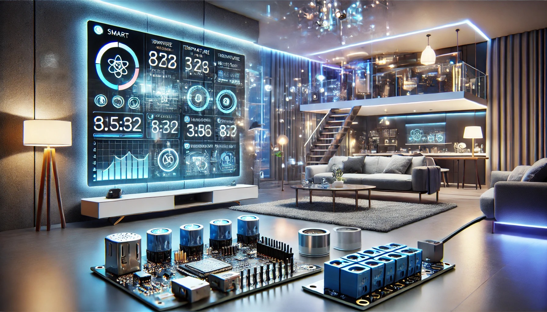

IoT-Based Smart Home Automation System Using ESP32
1. Introduction
This project focuses on home automation using ESP32, allowing users to remotely control appliances and monitor sensor data via a web dashboard. It connects to Wi-Fi and provides an interactive interface for real-time monitoring and control.
Real-World Applications:
- Smart Homes – Remote control of lights, fans, and appliances.
- Energy Management – Monitor power usage and improve efficiency.
- Security Systems – Integrate with motion sensors for alerts.
2. Learning Objectives
By completing this project, you will learn:
✅ How to interface ESP32 with relays and sensors
✅ How to build a web-based dashboard for IoT control
✅ How to use Wi-Fi communication with ESP32
✅ How to set up MQTT or HTTP server for remote access
3. Tools and Components
Hardware Requirements:
- ESP32 Development Board
- 4-Channel Relay Module (for appliance control)
- DHT11 or DHT22 Sensor (for temperature & humidity monitoring)
- AC Appliances (Bulb, Fan, etc.)
- 5V/12V Power Adapter
- Jumper Wires & Breadboard
Software Requirements:
- Arduino IDE (for ESP32 programming)
- ESPAsyncWebServer Library (to create the web dashboard)
- Blynk or MQTT broker (for remote access)
4. Circuit Breakdown & Wiring
ESP32 to Relay Module Wiring:
- ESP32 D23 → Relay IN1 (Controls Appliance 1)
- ESP32 D22 → Relay IN2 (Controls Appliance 2)
- ESP32 D21 → Relay IN3 (Controls Appliance 3)
- ESP32 D19 → Relay IN4 (Controls Appliance 4)
- ESP32 GND → Relay GND
- ESP32 5V → Relay VCC
Note: Use an external 5V power adapter for the relay if high current loads are involved.
ESP32 to DHT11/DHT22 Sensor Wiring:
- ESP32 D4 → DHT Data Pin
- ESP32 3.3V → DHT VCC
- ESP32 GND → DHT GND
AC Appliance Connection:
- The relay output is connected in series with the AC load (bulb/fan).
- When the relay is triggered, it allows current to flow, turning the appliance ON.
5. ESP32 Code for IoT Web Control
The following program:
✔ Reads temperature & humidity data from the DHT sensor.
✔ Hosts a web-based dashboard to control appliances.
✔ Uses Wi-Fi communication for remote access.
#include <WiFi.h>
#include <ESPAsyncWebServer.h>
#include <DHT.h>

#define DHTPIN 4
#define DHTTYPE DHT11
DHT dht(DHTPIN, DHTTYPE);

const char* ssid = "YOUR_WIFI_SSID";
const char* password = "YOUR_WIFI_PASSWORD";

AsyncWebServer server(80);

#define RELAY1 23
#define RELAY2 22
#define RELAY3 21
#define RELAY4 19

void setup() {
  Serial.begin(115200);
  WiFi.begin(ssid, password);

  while (WiFi.status() != WL_CONNECTED) {
    delay(1000);
    Serial.println("Connecting to WiFi...");
  }

  Serial.println("Connected to WiFi!");

  pinMode(RELAY1, OUTPUT);
  pinMode(RELAY2, OUTPUT);
  pinMode(RELAY3, OUTPUT);
  pinMode(RELAY4, OUTPUT);

  dht.begin();

  server.on("/", HTTP_GET, [](AsyncWebServerRequest *request){
    float temp = dht.readTemperature();
    float hum = dht.readHumidity();

    String html = "<html><body>";
    html += "<h2>Smart Home Dashboard</h2>";
    html += "<p>Temperature: " + String(temp) + "°C</p>";
    html += "<p>Humidity: " + String(hum) + "%</p>";
    html += "<a href='/on1'><button>Turn ON Device 1</button></a>";
    html += "<a href='/off1'><button>Turn OFF Device 1</button></a>";
    html += "</body></html>";

    request->send(200, "text/html", html);
  });

  server.on("/on1", HTTP_GET, [](AsyncWebServerRequest *request){
    digitalWrite(RELAY1, LOW); // Turns ON
    request->send(200, "text/html", "Device 1 Turned ON");
  });

  server.on("/off1", HTTP_GET, [](AsyncWebServerRequest *request){
    digitalWrite(RELAY1, HIGH); // Turns OFF
    request->send(200, "text/html", "Device 1 Turned OFF");
  });

  server.begin();
}

void loop() {
  // Nothing needed here, handled by AsyncWebServer
}
6. Testing & Debugging
✔ Step 1: Open the Serial Monitor and check if ESP32 connects to Wi-Fi.
✔ Step 2: Once connected, open a web browser and enter the ESP32’s IP address.
✔ Step 3: Test the ON/OFF buttons and check if the appliances respond.
✔ Step 4: If the relay doesn’t work, verify the voltage levels & wiring.
7. Enhancements & Future Upgrades
🔥 Voice Control: Integrate Google Assistant or Alexa for hands-free operation.
🔥 Mobile App: Use Blynk or MQTT Dashboard for a modern UI.
🔥 Energy Monitoring: Add a Current Sensor (ACS712) to track power consumption.
Final Thoughts
This ESP32-based IoT Smart Home project provides practical experience in sensor interfacing, Wi-Fi communication, and web development. You now have a scalable platform for building advanced home automation solutions! 🚀
Would you like a PCB design or an MQTT-based alternative for cloud connectivity? 😊