

This blog post is a continuation of Our series from blog posts To zephyrin which we have already discussed First steps with ZephyrPresent Understand zephyr’s flashing sampleAnd Zephyr: Implementing a device driver for a sensor.
In this fourth blog post in our series we will see how you can add support for the display panel in Zephyr, which is available on the STM32L562E DK Plank.
Looking for existing support
The display field on the STM32L562E DK rating card is managed by A St7789H2 Screen controller and is connected via an STM32 interface with the name micro controller FMC (Flexible memory controller). The FMC is a controller with which you can take on an interface with different memory shapes with a parallel interface. However, it can also communicate with display controllers using the Intel 8080 protocol. The following block diagram shows the display area connected via FMC (for display) and I2C (for touchscreen). This blog post is only about the display page connected via the FMC interface of the STM32 microcontroller.

In order to activate the display on this board, we first have to examine what is supported by Zephyr. The STM32 FMC supports available The device tree binding For the FMC and more precisely, The bond for the NOR/PSRAM part of the FMCwhich we use to communicate with the display controller.
For the display controller there is no specially for the ST7789H2, but there is support for the ST7789V. After checking the data sheets, we can find that there is essentially no difference between the two devices, so that support for the ST7789V for our display controller works.
The problem, however, is that the display controller can be controlled via different interfaces. Therefore, we have to ensure that the ST7789V can be controlled by the FMC and not by another device.
When we see each other The driver for the ST7789VWe can find that it does not access a device directly to communicate with the display controller. Instead, the driver uses the Zephyr Mipi DBI API. For example, consider the function st7789v_transmit:
static void st7789v_transmit(const struct device *dev, uint8_t cmd,
                 uint8_t *tx_data, size_t tx_count)
{
    const struct st7789v_config *config = dev->config;

    mipi_dbi_command_write(config->mipi_dbi, &config->dbi_config, cmd,
                   tx_data, tx_count);
}
This means that we need a Mipi DBI driver to link the FMC with a display controller. We can see all Mipi -DBI drivers in the drivers/mipi_dbi Folder. There are drivers for different devices, but not a driver for the FMC. So our first goal will be to write this driver.
The device tree
First of all, we have to decide how we can structure our device tree.
We can see how existing Boards Display Panels represent in the device tree, e.g. B. the ST7789V, even if this is done via another interface. We can use this git grep To find the device tree of a board with this display controller: git grep st7789v.
For example, we see that the board M5stack Atome3 has ST7789V Display controller that is described as follows:
    mipi_dbi {
        compatible = "zephyr,mipi-dbi-spi";
        spi-dev = <&spi2>;
        /* ... */

        st7789v: st7789v@0 {
            compatible = "sitronix,st7789v";
            /* Properties for the st7789v */
        };
    };
We see that we have to set our display controller in A mipi_dbi Node. This knot does not represent a actual device: In this case, the actual device for communication with the ST7789V is spi2named on the use of the spi-dev Device tree property.
Next we have to find out how to describe the FMC. The bond Show us how to do it:
&fmc {
    pinctrl-0 = <...>;
    pinctrl-names = "default";
    status = "okay";

    sram {
        compatible = "st,stm32-fmc-nor-psram";

        #address-cells = <1>;
        #size-cells = <0>;

        bank@0 {
            reg = <0x0>;
            st,control = <...>;
            st,timing = <...>;
        };
    };
};
To understand this device tree, we have to learn something about the FMC. The FMC has four banks (256 MB each each), one for NOR/PSRAM storage and three for NAND storage. The bank for the NOR/PSRAM memory is divided into four lower banks. For the LCD we have to use the NOR/PSRAM bank. Depending on the required specific subbank that bank The knot must have a different rain value (bank@0 For the first underbank, bank@1 for the second etc.). As explained in the Data sheet:

We now have to decide where to set our Mipi DBI device. Similar to the mipi-dbi-spi Knotes we have seen before will not be a real device, but the ST7789V assumes that it is in a knot with a Mipi DBI driver. We will be in the places bank@0 Node.
So our device tree looks like this:
    //...

    bank@0 {
        reg = <0x0>;
        st,control = <...>;
        st,timing = <...>;

        fmc-mipi-dbi {
            compatible = "st,stm32-fmc-mipi-dbi";

            st7789v: lcd-panel@0 {
                compatible = "sitronix,st7789v";
                // ...
            };
        };
    };
Now it is important to set the properties of the FMC st,control And st,timing. These properties are used by the FMC driver to configure the FMC. We can refer to the bond to see the meanings of the different values of these two properties. To find the values we need, we can see each other The BSP From st. In Drivers/BSP/STM32L562E-DK/stm32l562e_discovery_lcd.cWe find a function that sets the FMC. Thanks to this function, we can now derive the values of the two properties:
    st,control = <STM32_FMC_DATA_ADDRESS_MUX_DISABLE
        STM32_FMC_MEMORY_TYPE_SRAM
        STM32_FMC_NORSRAM_MEM_BUS_WIDTH_16
        STM32_FMC_BURST_ACCESS_MODE_DISABLE
        STM32_FMC_WAIT_SIGNAL_POLARITY_LOW
        STM32_FMC_WAIT_TIMING_BEFORE_WS
        STM32_FMC_WRITE_OPERATION_ENABLE
        STM32_FMC_WAIT_SIGNAL_DISABLE
        STM32_FMC_EXTENDED_MODE_DISABLE
        STM32_FMC_ASYNCHRONOUS_WAIT_DISABLE
        STM32_FMC_WRITE_BURST_DISABLE
        STM32_FMC_CONTINUOUS_CLOCK_SYNC_ONLY
        STM32_FMC_WRITE_FIFO_DISABLE
        STM32_FMC_PAGE_SIZE_NONE>;

    st,timing = <1 1 32 0 2 2 STM32_FMC_ACCESS_MODE_A>;
Implementation of the driver
We then have to encode the Mipi DBI driver. First we have to create all the necessary files so that Zephyr can properly configure and compile the driver. First we create the file drivers/mipi_dbi/Kconfig.stm32_fmc:
config MIPI_DBI_STM32_FMC
	bool "MIPI DBI driver for STM32 FMC"
	default y
	depends on DT_HAS_ST_STM32_FMC_MIPI_DBI_ENABLED
	select MEMC
	help
	  Enable support for MIPI DBI driver for controller based on the STM32 FMC.

config MIPI_DBI_STM32_FMC_MEM_BARRIER
	bool "Adds memory barrier after every address and data register access"
	default y

endif # MIPI_DBI_STM32_FMC
The option MIPI_DBI_STM32_FMC_MEM_BARRIERAfter default, our driver must insert a storage barrier between every register access. These barriers are required on some systems.
In drivers/mipi_dbi/KconfigWe add this line:
source "drivers/mipi_dbi/Kconfig.stm32_fmc"
Next we add the following line to drivers/mipi_dbi/CMakeLists.txt:
zephyr_sources_ifdef(CONFIG_MIPI_DBI_STM32_FMC mipi_dbi_stm32_fmc.c)
We also have to create the device beam binding in dts/bindings/mipi-dbi/st,mipi-dbi-fmc.yaml:
description: STM32 FMC display controller
compatible: "st,stm32-fmc-mipi-dbi"

include: ("mipi-dbi-controller.yaml")

properties:
  reset-gpios:
    type: phandle-array
    description: |
      Reset GPIO pin. Set high to reset the display.

  power-gpios:
    type: phandle-array
    description: |
      Power GPIO pin. Set high to power the display.

  register-select-pin:
    type: int
    required: true
    description: |
      Address pin used as Register Select for the display controller.
We define three properties in our bond: reset-gpios And power-gpios Allow us to describe the two GPIOs that are used for the power supply and reset the lines. register-select-pin Allows us to indicate which PIN serves as “Select tab”, which we will discuss later.
We can now create our driver drivers/mipi_dbi/mipi_dbi_stm32_fmc.c.
Note that in this blog post we do not respond to the code that is common for most drivers. You can find an introduction to the development of Zephyr device device in our Previous blog post for implementing a device driver for a sensor.
The first thing to do is to be defined DT_DRV_COMPAT Zephyr goal for our driver:
#define DT_DRV_COMPAT st_stm32_fmc_mipi_dbi
Before you write the rest of our driver, it is important to understand how the FMC communicates with the display controller. The FMC offers a 16-bit parallel interface with the display controller. There is also a PIN named “Register Select” with which the display controller is given whether the data in the line is a command, or either a parameter for the command or an ad. On the other hand, the FMC sees the controller as a memory: it has pins for the data and for the address. The 16 data pins of the FMC are linked to the data pens of the display controller, and one of the address pencils is linked to the register selection. This is the importance of property register-select-pin We added that to the bond.
This means that if we want to send a command, we only have to write to the starting address of the memory bank (the address that the FMC sends is 0). If we want to write data in the display controller, we have to write to another address in which the bit of the address, which ends in the tab selection -PIN, is set to 1.
Now that we understand that, we can write the driver. First, we have to explain ours config And data Structures:
struct mipi_dbi_stm32_fmc_config {
	/* Reset GPIO */
	const struct gpio_dt_spec reset;
	/* Power GPIO */
	const struct gpio_dt_spec power;
	mem_addr_t register_addr;
	mem_addr_t data_addr;
	uint32_t fmc_address_setup_time;
	uint32_t fmc_data_setup_time;
	uint32_t fmc_memory_width;
};

struct mipi_dbi_stm32_fmc_data {
	const struct mipi_dbi_config *dbi_config;
};
The properties register_addr And data_addr Are the two addresses that we talked about before. The properties fmc_address_setup_timePresent fmc_data_setup_timeAnd fmc_memory_width are only properties of the FMC with which we check whether the FMC is correctly configured.
We then have to have a way to calculate register_addr And data_addr.
First, register_addr. This is simple: if we are on the first base bank, we only have to use the definition of the St. Hal. FMC_BANK1_1. If we are a second, use FMC_BANK1_2etc. We just have to be careful because the reg Property in the device tree is 0 for the first bank, but we want a 1 In the name. This gives us this macro:
#define MIPI_DBI_FMC_GET_ADDRESS(n) \
        _CONCAT(FMC_BANK1_, UTIL_INC(DT_REG_ADDR(DT_INST_PARENT(n))))
Next we have to calculate data_addr. The formula is register_addr + (1 << (register_select + 1)): We put the right bit on 1. The bits of the bus that is not wired when register_select is 0, we have to use bit 1, hence the + 1.
#define MIPI_DBI_FMC_GET_DATA_ADDRESS(n)                                                           \
	MIPI_DBI_FMC_GET_ADDRESS(n) + (1 << (DT_INST_PROP(n, register_select_pin) + 1))
We can now declare the macro with which we can create our device and fill the configuration structure:
#define MIPI_DBI_STM32_FMC_INIT(n)                                                                 \
	static const struct mipi_dbi_stm32_fmc_config mipi_dbi_stm32_fmc_config_##n = {            \
		.reset = GPIO_DT_SPEC_INST_GET_OR(n, reset_gpios, {}),                             \
		.power = GPIO_DT_SPEC_INST_GET_OR(n, power_gpios, {}),                             \
		.register_addr = MIPI_DBI_FMC_GET_ADDRESS(n),                                      \
		.data_addr = MIPI_DBI_FMC_GET_DATA_ADDRESS(n),                                     \
		.fmc_address_setup_time = DT_PROP_BY_IDX(DT_INST_PARENT(n), st_timing, 0),         \
		.fmc_data_setup_time = DT_PROP_BY_IDX(DT_INST_PARENT(n), st_timing, 2),            \
		.fmc_memory_width = DT_PROP_BY_IDX(DT_INST_PARENT(n), st_control, 2),              \
	};                                                                                         \
                                                                                                   \
	static struct mipi_dbi_stm32_fmc_data mipi_dbi_stm32_fmc_data_##n;                         \
                                                                                                   \
	DEVICE_DT_INST_DEFINE(n, mipi_dbi_stm32_fmc_init, NULL, &mipi_dbi_stm32_fmc_data_##n,      \
			      &mipi_dbi_stm32_fmc_config_##n, POST_KERNEL,                         \
			      CONFIG_MIPI_DBI_INIT_PRIORITY, &mipi_dbi_stm32_fmc_driver_api);

DT_INST_FOREACH_STATUS_OKAY(MIPI_DBI_STM32_FMC_INIT)
Note that we use the function here mipi_dbi_stm32_fmc_init And the variable mipi_dbi_stm32_fmc_driver_apiWhat we will define now.
First of all, the initialization is: our code is quite simple. Simply configure the two GPIOs (reset and electricity) to the correct output.
static int mipi_dbi_stm32_fmc_init(const struct device *dev)
{
	const struct mipi_dbi_stm32_fmc_config *config = dev->config;

	if (config->reset.port) {
		if (!gpio_is_ready_dt(&config->reset)) {
			LOG_ERR("Reset GPIO device not ready");
			return -ENODEV;
		}

		if (gpio_pin_configure_dt(&config->reset, GPIO_OUTPUT_INACTIVE)) {
			LOG_ERR("Couldn't configure reset pin");
			return -EIO;
		}
	}

	if (config->power.port) {
		if (!gpio_is_ready_dt(&config->power)) {
			LOG_ERR("Power GPIO device not ready");
			return -ENODEV;
		}

		if (gpio_pin_configure_dt(&config->power, GPIO_OUTPUT)) {
			LOG_ERR("Couldn't configure power pin");
			return -EIO;
		}
	}

	return 0;
}
Next we have to implement the API functions that the display controller calls.
We will implement three functions, all part of the MIPI -DBI -API: mipi_dbi_reset()Present mipi_dbi_command_write()And mipi_dbi_write_display().
The reset function is simple: Simply set the reset -pin to 1, wait for the corresponding delay and then set it to 0.
static int mipi_dbi_stm32_fmc_reset(const struct device *dev, uint32_t delay)
{
	const struct mipi_dbi_stm32_fmc_config *config = dev->config;
	int ret;

	if (config->reset.port == NULL) {
		return -ENOTSUP;
	}

	ret = gpio_pin_set_dt(&config->reset, 1);
	if (ret reset, 0);
}
Then we have to tackle the two main functions mipi_dbi_command_write() And mipi_dbi_write_display(). These two functions last as parameters a pointer on A struct mipi_dbi_config. It is important to check whether our FMC is compatible with the configuration required by the display controller.
First we have to check whether the display controller asks for the right MIPI DBI mode: Intel 8080 to 16 bit. We also have to check whether the FMC is configured for a 16 -bit bus. We also have to check whether the FMC’s writing frequency is compatible with the frequency of the display controller. The FMC frequency can be calculated as follows (removed from from removed from The application note An2784:

We only have to compare it to the frequency specified in the specified frequency struct mipi_dbi_config.
In order not to check the same configuration every time, in our data structure we save a pointer to the configuration that has just been checked so that we only have to check whether the two hands are the same next time.
int mipi_dbi_stm32_fmc_check_config(const struct device *dev,
				    const struct mipi_dbi_config *dbi_config)
{
	const struct mipi_dbi_stm32_fmc_config *config = dev->config;
	struct mipi_dbi_stm32_fmc_data *data = dev->data;
	uint32_t fmc_write_cycles;

	if (data->dbi_config == dbi_config) {
		return 0;
	}

	if (dbi_config->mode != MIPI_DBI_MODE_8080_BUS_16_BIT) {
		LOG_ERR("Only support Intel 8080 16-bits");
		return -ENOTSUP;
	}

	if (config->fmc_memory_width != FMC_NORSRAM_MEM_BUS_WIDTH_16) {
		LOG_ERR("Only supports 16-bit bus width");
		return -EINVAL;
	}

	uint32_t hclk_freq =
		STM32_AHB_PRESCALER * DT_PROP(STM32_CLOCK_CONTROL_NODE, clock_frequency);

	/* According to the FMC documentation*/
	fmc_write_cycles =
		((config->fmc_address_setup_time + 1) + (config->fmc_data_setup_time + 1)) * 1;

	if (hclk_freq / fmc_write_cycles > dbi_config->config.frequency) {
		LOG_ERR("Frequency is too high for the display controller");
		return -EINVAL;
	}

	data->dbi_config = dbi_config;
	return 0;
}
The mipi_dbi_stm32_fmc_command_write() It is now easy to write: After we have checked whether the configuration is correct, we have to write the command register_addrand then write down all parameters data_addr.
int mipi_dbi_stm32_fmc_command_write(const struct device *dev,
				     const struct mipi_dbi_config *dbi_config, uint8_t cmd,
				     const uint8_t *data_buf, size_t len)
{
	const struct mipi_dbi_stm32_fmc_config *config = dev->config;
	int ret;
	size_t i;

	ret = mipi_dbi_stm32_fmc_check_config(dev, dbi_config);
	if (ret < 0) {
		return ret;
	}

	sys_write16(cmd, config->register_addr);
	if (IS_ENABLED(CONFIG_MIPI_DBI_STM32_FMC_MEM_BARRIER)) {
		barrier_dsync_fence_full();
	}

	for (i = 0U; i < len; i++) {
		sys_write16((uint16_t)data_buf(i), config->data_addr);
		if (IS_ENABLED(CONFIG_MIPI_DBI_STM32_FMC_MEM_BARRIER)) {
			barrier_dsync_fence_full();
		}
	}

	return 0;
}
The function mipi_dbi_stm32_fmc_write_display It’s even easier: we only have to write the picture in the memory without writing an command.
static int mipi_dbi_stm32_fmc_write_display(const struct device *dev,
					    const struct mipi_dbi_config *dbi_config,
					    const uint8_t *framebuf,
					    struct display_buffer_descriptor *desc,
					    enum display_pixel_format pixfmt)
{
	const struct mipi_dbi_stm32_fmc_config *config = dev->config;
	size_t i;
	int ret;

	ret = mipi_dbi_stm32_fmc_check_config(dev, dbi_config);
	if (ret < 0) {
		return ret;
	}

	for (i = 0U; i < desc->buf_size; i += 2) {
		sys_write16(sys_get_le16(&framebuf(i)), config->data_addr);
		if (IS_ENABLED(CONFIG_MIPI_DBI_STM32_FMC_MEM_BARRIER)) {
			barrier_dsync_fence_full();
		}
	}

	return 0;
}
We only have to declare our API structure:
static struct mipi_dbi_driver_api mipi_dbi_stm32_fmc_driver_api = {
	.reset = mipi_dbi_stm32_fmc_reset,
	.command_write = mipi_dbi_stm32_fmc_command_write,
	.write_display = mipi_dbi_stm32_fmc_write_display,
};
Our code now works. To test it, we can carry out the sample display:
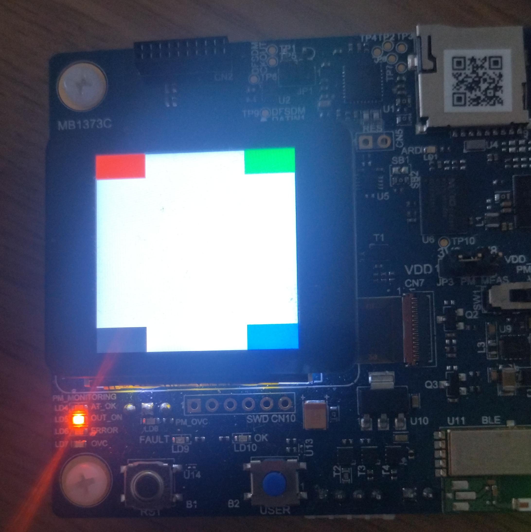
Diploma
In this blog post you learned how the interface between the STM32 -FMC and a display controller in Zephyr works with the Mipi -DBI -API. The entire code in this blog can be seen in the Related pull request on Github, which has been accepted upstream since then.
Stay tuned for more blog posts with Zephyr!