

IoT Home Monitoring and Automation System
Introduction
This project will create a smart home system using the ESP32 microcontroller. The system will:
- Monitor environment variables: temperature, humidity, and light intensity.
- Control appliances: using relays for connected devices like lights and fans.
- Send data to a cloud platform for real-time monitoring and visualization.
- Allow control via a mobile app (Blynk or a custom-developed app).
Real-world Applications:
- Home automation
- Smart offices
- Remote environmental monitoring
- Energy-saving systems
Learning Objectives
By the end of this project, you will learn:
- How to interface sensors and relays with ESP32.
- Use the ESP32 for wireless communication (Wi-Fi).
- Send sensor data to a cloud platform (e.g., ThingSpeak or Blynk).
- Control appliances remotely through a mobile app.
- Build an efficient and reliable circuit for IoT applications.
Tools and Components
Hardware
- ESP32 Dev Module (1x)
- DHT22 (or DHT11) Temperature and Humidity Sensor (1x)
- LDR (Light Dependent Resistor) for light intensity sensing (1x)
- 10kΩ Resistor (for the LDR circuit)
- Relay Module (2-channel) for appliance control
- Breadboard and connecting wires
- 5V Power Supply
- Appliances for control (e.g., LED lamp, fan)
Software
- Arduino IDE (for programming the ESP32)
- Blynk mobile app or ThingSpeak (for cloud monitoring)
- Serial Monitor (for testing and debugging)
Background and Definitions
- ESP32: A powerful microcontroller with built-in Wi-Fi and Bluetooth capabilities, ideal for IoT applications.
- DHT22 Sensor: Measures temperature and humidity with good accuracy.
- LDR: A Light Dependent Resistor whose resistance decreases with increasing light intensity.
- Relay Module: Acts as a switch to control high-power appliances.
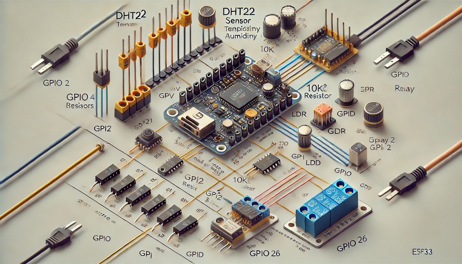
Circuit Diagram Explanation
The circuit is divided into two parts: sensor connections and appliance control. Here’s how the components will be connected:
- ESP32 Pin Configuration:
- DHT22 → GPIO 4
- LDR (through a voltage divider) → GPIO 36 (Analog Input)
- Relay 1 (for light) → GPIO 25
- Relay 2 (for fan) → GPIO 26
- Power Supply:
- The ESP32 is powered via a 5V USB supply.
- The relay module is powered using the 5V pin on the ESP32.
Circuit Diagram Description:
- The DHT22 sensor has three pins: VCC, GND, and DATA. Connect DATA to GPIO 4.
- For the LDR, use a 10kΩ resistor in a voltage divider configuration. The analog voltage from this divider is fed to GPIO 36.
- The relay module control pins are connected to GPIO 25 and GPIO 26 to control the light and fan, respectively.
Step-by-Step Guide
- Install ESP32 Board in Arduino IDE
Follow these steps to install ESP32 support in Arduino IDE:- Open Arduino IDE and go to File > Preferences.
- In the Additional Board Manager URLs, add this link:
https://dl.espressif.com/dl/package_esp32_index.json - Go to Tools > Board > Board Manager and install “esp32 by Espressif Systems”.
- Connect the Hardware
Assemble the circuit as per the diagram described earlier. Ensure the following:- The power supply is stable.
- Use proper connections for the relay to avoid short circuits.
- Write the Code
Upload the following code to your ESP32 using the Arduino IDE.
Source Code
#include <WiFi.h>
#include <DHT.h>
#include <BlynkSimpleEsp32.h>

#define DHTPIN 4
#define DHTTYPE DHT22
#define LIGHT_SENSOR_PIN 36
#define RELAY1 25
#define RELAY2 26

char auth[] = "YOUR_BLYNK_AUTH_TOKEN";
char ssid[] = "YOUR_WIFI_SSID";
char pass[] = "YOUR_WIFI_PASSWORD";

DHT dht(DHTPIN, DHTTYPE);
BlynkTimer timer;

void setup() {
  Serial.begin(115200);
  dht.begin();
  pinMode(RELAY1, OUTPUT);
  pinMode(RELAY2, OUTPUT);
  WiFi.begin(ssid, pass);
  Blynk.begin(auth, ssid, pass);

  timer.setInterval(2000L, sendSensorData);
}

void sendSensorData() {
  float temp = dht.readTemperature();
  float hum = dht.readHumidity();
  int lightLevel = analogRead(LIGHT_SENSOR_PIN);

  if (isnan(temp) || isnan(hum)) {
    Serial.println("Failed to read from DHT sensor!");
    return;
  }

  Blynk.virtualWrite(V1, temp);
  Blynk.virtualWrite(V2, hum);
  Blynk.virtualWrite(V3, lightLevel);

  Serial.print("Temp: ");
  Serial.print(temp);
  Serial.print(" °C, Humidity: ");
  Serial.print(hum);
  Serial.print(" %, Light: ");
  Serial.println(lightLevel);
}

void loop() {
  Blynk.run();
  timer.run();
}
Testing and Debugging Tips
- Sensor Readings Not Showing:
- Check the wiring of the DHT22 and ensure it’s getting power.
- Use the Serial Monitor to verify sensor output.
- Relay Not Switching:
- Verify relay module connections.
- Check that GPIO pins 25 and 26 are configured correctly.
- Wi-Fi Connection Issues:
- Ensure the SSID and password are correct.
- Bring the ESP32 closer to the Wi-Fi router for better signal strength.
Extensions and Future Enhancements
- Add more sensors: Motion sensors, gas sensors, or water leakage sensors for a comprehensive smart home system.
- Control via voice commands: Integrate with Google Assistant or Alexa.
- Data logging: Store sensor data in a database for long-term monitoring.
- Energy efficiency analysis: Use the data to create reports on power usage.